Driving Piezoelectric Actuators
Piezoelectric Drivers
Capacitance versus Voltage Range and TemperatureCare must be taken when interpreting capacitance values since these are measured at room temperature under small signal conditions. When an actuator is driven at full range, hysteresis exhibited by the piezoelectric material results in higher current flow. The effective capacitance at full-range is typically factor of 1.4 to 2.0 times the small signal capacitance; therefore, the effective capacitance is usually considered to be twice the small signal capacitance when the actuator is driven at full range. In addition to capacitance non-linearity, piezoelectric ceramics are also temperature dependant. The sensitivity and capacitance of common piezoelectric actuators can double with every 50 degrees Celsius increase in temperature. If the ambient temperature is above 25 degrees Celsius, the capacitance increase should be considered. Large temperature increases can also occur when driving piezoelectric actuators at high-speed or full-range. |
Current and Power CalculatorThe spreadsheet below calculates the maximum operating frequency of PiezoDrive amplifiers with a capacitive load. The second spreadsheet calculates the current, power, slew-rate, and approximate actuator heat dissipation. The spreadsheets do not take all operating conditions in to consideration and should only be used as a guide. More detailed specifications can be found in the amplifier datasheets. [back to top] |
Current Limit Equations
To avoid damage, piezoelectric drives contain circuitry to limit the maximum output current and power dissipation. These limits impose constraints on the dynamic performance of a piezoelectric actuator. As piezoelectric actuators can be approximated by a capacitance at low frequencies, the required drive current is proportional to the rate-of-change in voltage; that is, the required current is approximately
where C is the capacitance and V is the voltage. For a sine-wave, the maximum required current is
where Vpp is the peak-to-peak voltage. The above equation implies that the maximum sinewave frequency is
If a sinewave spans the full voltage range of the drive, the maximum frequency sinewave is also referred to as the power bandwidth. Compared to a sine-wave, a triangle wave requires less current, and allows a higher maximum frequency of:
An example of the voltage and current waveforms applied to a piezoelectric actuator are shown on the right. An Example of the Voltage and Current Required to Drive a Piezoelectric Actuator
The voltage and current required to drive a 330nF actuator at 5kHz Example: A 1uF piezoelectric actuator is to be driven by a 200Vpp, 30Hz sine-wave, the required current is
|
Voltage RangeThe output voltage range is the first consideration to be taken into account when selecting a drive for piezoelectric actuators. To achive maximum displacement, the drive should be capable of developing the full rated actuator voltage.
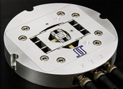
High-speed nanopositioner developed at the EASY lab, University of Nevada, Reno. Popular monolithic stack actuators are available in voltage ratings from 60V to 200V. This rating is the maximum positive voltage or coercive field strength that can be applied. Although higher than rated positive voltages will generally not damage an actuator, excessively high voltages may result in arcing that can erode the actuator and cause intermittent short circuits. Piezoelectric actuators can also tolerate small negative voltages. This will increase the actuators range but extreme care must be taken not to depolorize the dielectric. Most piezoelectric dielectrics can tolerate a negative voltage of approximately 10% to 20% of the maximum positive voltage. |
Signal Bandwidth
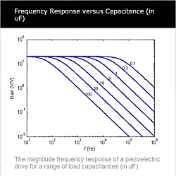
When considering small signals that do not exceed the current limit, the maximum operating frequency is dictated by the driver bandwidth. The bandwidth is the frequency where output power has reduced by a factor of two and significant phase-shift is present. For accurate signal reproduction, input frequencies should generally be lower than 10% of the driver bandwidth. As load capacitance is increased, the bandwith of a piezoelectric drive reduces. This relationship between capacitance and bandwidth can be found in the drive's datasheet. A typical frequency response characteristic is shown on the right. |
SafetyPiezoelectric drives produce hazardous potentials and should be used by suitably qualified personnel under the supervision of an observer with appropriate first-aid training. Do not operate piezoelectric drives when there are exposed conductors. |
Further ReadingA more detailed discussion of piezoelectric drive limitations can be found in the following references:
|