Piezoelectric Transformers - Operation
To drive a PT, either a sine wave or a square wave voltage can be used. In general, a sine wave voltage is preferred for minimizing the circulating energy through the shunt input capacitance Cd1 characteristic of the input of PT. However, generating a sine wave requires more reactive components in the driving circuit than a square wave. Therefore, using a square wave voltage in combination with some technique to minimize the switching loss is preferable. Such a combination is the so-called Zero Voltage Switching, ZVS, technique. The combination of the ZVS technique and the PT can reduce the capacitive turn-on loss due to the input capacitance Cd1 of the PT, and achieve high efficiency.
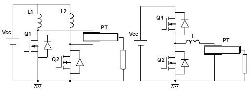
The general schematic adopted to drive a PT is illustrated in Figure 2. A DC-voltage is converted into a square wave voltage, which is applied to the piezoelectric transformer. The generated voltage at the output is supplied to the load. Depending on the application it may be rectified first. Work on different resonant switching converters topologies have been published, including push-pull, half-bridge, full-bridge and flyback. Figure 2 shows the two more common topologies presented in commercial applications, the push-pull and the half-bridge. From all of them, the standard approach used for step-up applications has been the push-pull topology, since allow higher step-up ratios than half-bridge and has a simpler driving control circuit for the transistors gates. However, half-bridge has been generally adopted for power applications in the recent publications.
In order to ensure the stability of the output voltage or current under fluctuations of load or variations of input voltage, the control of the switching converter require from a feedback circuit.
There are two basic approaches to drive a PT while allowing regulation of the output: i) at fixed frequency and changing the input gate duty cycle (duty cycle control or PWM control); ii) by varying the driving frequency (frequency control or PFM control). Each of these two techniques has some limitations as well as some benefits and drawbacks. In some cases, it is possible and required to implement both of them to obtain the wider regulation range and maximum efficiency of your application.
The most extended strategy to control the operation of the PT is to vary the driving frequency accordingly to a change of the load operation or the input voltage. This control is called ?frequency control?. The frequency control requires one or several feedback loops which provide information about how the output voltage (or current) is changing so it can be appropriately corrected. There are several possibilities that have been proposed:
- Frequency control by measuring the output voltage.
- Frequency control by measuring the output current.
- Frequency control by measuring the input to output voltage phase difference.
- Frequency control by measuring the input voltage and current phase difference.
In the first control strategy, the secondary voltage of the transformer is measured. This information is compared with a reference value by a comparator for controlling a driving frequency of the driving circuit. In this way, the output current of the output load, for instance a CCFL lamp, can be constantly maintained, even when environmental temperature, power supply voltage Vin or load condition is varied. However, in this control method, when a fluctuation of a power source to be supplied to the system is large or in case of load causing load fluctuation, it is inevitable to operate at the frequency where the efficiency is low.
The second type of control is similar, however, typically the output current is detected by a resistor and converted into a direct current level by a rectifying circuit to control the driving frequency control. To this type of control correspond the family UCC3975, 6, 9 of IC driving circuits for PTs developed by Texas Instruments and available commercially since late 2001.
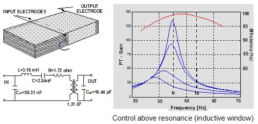
The third type of frequency control measures the input and output phase difference and adjust the driving circuit frequency accordingly to obtain maximum efficiency conditions based on the phase difference.The tracking of the resonance frequency is obtained by comparing the input voltage and current. Input impedance of the PT shows capacitive behavior at frequencies lower than resonance. At frequencies between resonance (lowest value of input impedance) and anti-resonance (highest value of input impedance) the impedance is inductive, then again becomes capacitive. Thus, the phase between voltage and current varies from ?90o to +90o during the three intervals. At resonance the phases of the fundamental harmonics of input current and voltage must be the same, therefore a phase frequency detector (PFD) circuit is adopted to synchronize voltage and current. Typically, the input current signal is sensed by the shunt resistor RCS, then filtered to avoid spurious spikes due to the charge and discharge of the PT input capacitance, and is finally squared by applying it to a voltage comparator. As the output of the half-bridge driver is also a square wave, it is sent directly in to the PFD.
The use of a single frequency loop cannot ensure the perfect control of the PT under big variations of input voltage and/or load fluctuations. When this happens the frequency shift required in the transformer to adjust the output conditions may be too large that the efficiency of the PT is significantly affected or/and that the correct transformation ratio to achieve the expected values.
In order to overcome these limitations, a second voltage feedback loop control has been typically added in the latest driving control strategies. The voltage feedback has been implemented in two basic ways. One alternative has been proposed that control the duty cycle of the driving circuit signal of the transistor gates. The second alternative includes the control of the input DC voltage by using a chopper circuit controlled at much lower frequency than the PT, 100Hz, which switch the input voltage to the switching transistor. Several IC companies such as Rohm, Sanyo, O2 micro and others are currently developing and commercially providing IC controllers for PT integrating frequency and voltage control loop in addition to other features such as dimming control and open and short-circuit condition protection.