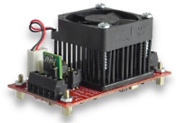
PDm200 Miniature High Voltage Amplifier
Piezoelectric Drivers
 PDm200 Specifications
 Calculate Power Bandwidth
Specifications:
| PDm200 Specifications | |||
|---|---|---|---|
| Power Supply | +/-12 V to +34 V | ||
| Max. Unipolar Output | -30 V to 200 V | ||
| Max. Bipolar Output | +/-200 V | ||
| Peak Output Current | 300 mA | ||
| RMS Output Current | 120 mA (+/-100 V Output) | ||
| Power Bandwidth | 63 kHz (100 Vp-p) | ||
| Signal Bandwidth | 200 kHz | ||
| Slew Rate | 20 V/us | ||
| Dimensions | 71 x 38 mm | ||
| Weight | 50 g | ||
| Gain | 20 V/V | ||
| Input Impedance | 200 kOhm | ||
| Input Offset | +/- 10 mV | ||
| Load | Any | ||
| Overload Protection | Thermal and current | ||
| Noise | 1 mV RMS (1uF Load) | ||
| Environment | 0 to 60 C (32 to 140 F) | ||
| Quiescent Current | 100 mA (7.5 mA in Shutdown) | ||
Features
The PDm200 is a high-performance power supply and linear amplifier module for driving piezoelectric actuators and other loads. The output voltage range can be switched between bipolar or unipolar modes with a range of 100V, 150V, or 200V. In the unipolar mode, the negative output range is fixed at -30V for use with stack actuators. The PDm200 can drive stack actuators; standard piezoelectric actuators; two wire benders; and three-wire piezoelectric benders requiring a bias voltage.
The PDm200 is suited to a wide range of applications including: Electro-optics, ultrasound, vibration control, nanopositioning systems, and piezoelectric motors. There is short-term protection for over-current and temperature. The module can be mounted to a base with four M2.5 screws. The PCB mounting version is supplied with headers for direct mounting onto a host motherboard.
| Compatible Actuators | |||
|---|---|---|---|
| Stack Actuators | 60V, 100V, 120V, 150V, 200V | ||
| Plates and Tubes | up to +/- 200V | ||
| Two Wire Benders | up to +/- 200V | ||
| Three Wire Benders | 0 to 200V with 200 V bias | ||
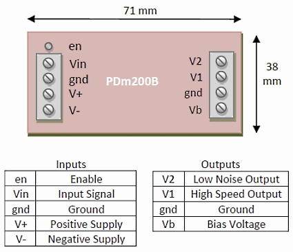
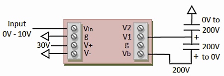
Connection Diagram
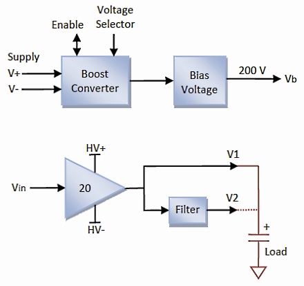
Operation
A power converter generates a unipolar or bipolar supply. The output voltage range is controlled by the voltage selector jumpers. The amplifier has a gain of 20 and an input voltage range of +/-10 V. The load is connected directly to the high-speed output (V1) or through a filter (V2) which reduces the noise and bandwidth. In most applications, the V2 output is recommended.
A variable bias supply is also available for piezoelectric bender applications. The default bias voltage is 200 V but lower voltages can be achieved by adding a resistor
Example Applications
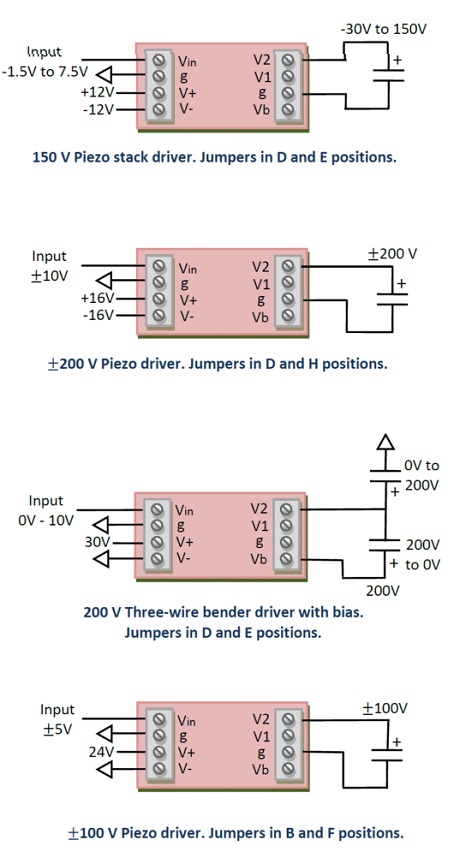
Configuration
The PDm200 is configurable to suit a wide range of power supply and output voltage ranges. The output voltage range is selected by two jumpers marked L1 and L2, as shown below. Each jumper has four possible positions marked by the letters A to D and E to H.
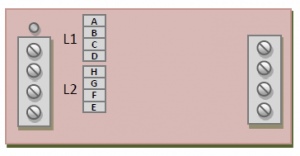
In the unipolar output mode, the negative output range is fixed at -30 V and the jumper L2 is always in the ‘E’ position. The correct position for the L1 jumper is listed below for different power supply voltages.
| Output Voltage | Power Supply Voltage | ||||
|---|---|---|---|---|---|
| Max | Min | +/-12 to +/-14V | +/-15 to +/-17V | +24V* to 30V | +30V* to 34V |
| 200V | -30V | D | D | ||
| 150V | -30V | D | C | D | C |
| 120V | -30V | C | B | C | B |
| 100V | -30V | B | A | B | A |
*With a single supply, the negative output voltage range is reduced from -30 V to -20 V.
In bipolar output mode, the correct positions for the L1 and L2 jumpers are listed in below.In the +/-200 V mode, the low-noise output (V2) is recommended. See “Stability” for more details.
| Output Voltage | Power Supply Voltage | ||||
|---|---|---|---|---|---|
| max | Min | +/-12 to +/-14V | +/-15 to +/-17V | +24V to 30V | +30V to 34V |
| 200V | -200V | D,H | D,H | ||
| 150V | -150V | D,H | C,G | D,H | C,G |
| 100V | -100V | B,F | A,F | B,F | A,F |
The PDm200 can also be used in lower voltage applications; however, the output current may be reduced. The corresponding low-voltage jumper positions are listed below
| Output Voltage | Power Supply Voltage | ||
|---|---|---|---|
| max | Min | +/-12V to +/-14V | +12V to +15V |
| 80V | -30V | A,E | |
| 80V | 0V | D,E | |
| 60V | -60V | D,H | |
Output Current
The peak output current is approximately 300 mA and the maximum average DC output current is approximately
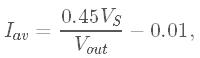
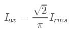
where VS is the differential supply voltage e.g. 30V, and Vout is the differential output voltage range e.g. 400V. The average DC current is the average current flowing in either the positive or negative direction. For a sine wave, the average DC current is related to the RMS current by
The PDm200 calculator can be used to estimate the maximum input and output current for a given supply voltage and output voltage range. Some common values are tabulated below.
| Output Voltage | RMS Current | Average Current | |
|---|---|---|---|
| max | Min | ||
| 150V | -30V | 144 mA | 65 mA |
| 200V | -30V | 108 mA | 49 mA |
| 100V | -100V | 128 mA | 58 mA |
| 200V | -200V | 53 mA | 24 mA |
Supply Current
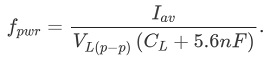
The maximum supply current is 0.5 A at full load. For a partial load, the supply current is 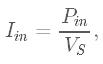
where the required input power is ![]()
where Vout is the differential output voltage range and Iav is the average output current.
Power Bandwidth
The calculator accessed below plots the maixmum peak-to-peak output voltage for a capacitive load versus the frequency and voltage range.
Calculate Power Bandwidth
With a capacitive load, the power bandwidth is limited by the average output current. The maximum frequency sine wave is
The power bandwidth is primarily related to the average current limit as described above. However, when operating at full range, e.g. +/-200 V, with the minimum supply voltage, e.g. +/-15 V, the power supply droop can distort the top of a signal. This effect can be reduced by increasing the supply voltage.
Signal Bandwidth
With a load capacitance greater than 100 nF, the small signal bandwidth is 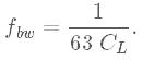
With a load capacitance less than 100 nF, the small signal bandwidth is approximately 200 kHz. The bandwidth of the low noise output (V2) is approximately 5% of the high speed output, that is, 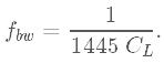
The small signal bandwidth for a range of capacitive loads is listed in the table below.
| Load Capacitance | High Speed Bandwidth | Low Noise Bandwidth |
|---|---|---|
| 10 nF | 200 kHz | 49 kHz |
| 30 nF | 200 kHz | 20 kHz |
| 100 nF | 158 kHz | 6.6 kHz |
| 300 nF | 52 kHz | 2.3 kHz |
| 1 uF | 15 kHz | 690 kHz |
| 3 uF | 5.2 kHz | 230 kHz |
| 10 uF | 1.5 kHz | 69 Hz |
| 30 uF | 530 Hz | 23 Hz |
Noise
The output of the PDm200 contains a small amount of switching noise from the boost converter and random noise from the high-voltage amplifier. With a +/-15 V supply and +/-100 V output range, the RMS noise is listed below.
| Load Capacitance | High Speed Output | Low Noise Output |
|---|---|---|
| 10 nF | 4.1 mV* | 1 mV |
| 100 nF | 1.3 mV* | 0.3 mV |
| 1 uF | 1.3 mV | 0.2 mV |
| 10 uF | 0.42 mV | 0.1 mV |
For applications requiring extremely low noise, a larger resistance can be used to reduce the effective bandwidth, which is approximately
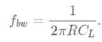
where CL is the load capacitance. The recommended bandwidth in low-noise applications is 100 Hz. The noise measurements were performed with the input shorted. The noise may increase when significant current is drawn from the output due to ripple from the boost converter.
*For load capacitances of 100nF or smaller, the low noise output (V2) is recommended.
The noise from the PDm200 internal switching power supply includes a common-mode noise current that flows into the module ground. This can appear as fast voltage ‘spikes’ that occur at intervals of approximately 2.5us on the input and output signals, and the power supply connections.
- Common-mode noise is exacerbated by ground loops and wiring inductance. To reduce the common-mode noise, the following techniques can help:
- Use a twisted pair (for single supplies) or a braided triple (for dual supplies) to connect the module to the power supply. Minimize inductance by using a tight braid or twist.
- Use a separate twisted pair to connect the input signals, and the load.
- For further reduction, wind 5 to 10 turns of the twisted pair or braid around an ungapped ferrite toroid, e.g. a 1-inch Fair-Rite 5975001401. There should be a 1mm gap between adjacent turns, do not let the turns contact each other.
It should be noted that the common-mode noise is approximately equal on the output signal and ground; therefore, if there is no separate connection to an external ground at the load, the common-mode noise will not result in a significant voltage difference at the load.
Standard oscilloscope probes are grounded and will exaggerate the effect of common-mode noise. To measure the true output noise at the piezo, a differential or isolated probe is required. If this is not available, a high-frequency isolation transformer in series with an AC decoupling capacitor is possible.
Application Notes
The amplifier input Vin should not be left floating as it will drift towards a supply rail. However, in applications where the input may float, a 1 kOhm resistor (1206 size) can be mounted at the location “Rin”, the input impedance is now 1 kOhm.
Heat Dissapation
At full power, the worst-case heat dissipation is approximately 15 W which is dissipated by the heatsink and fan. During normal operation the heat dissipation can be estimated by multiplying the required supply current and the differential supply voltage.
When the heat dissipation is less than 5W, the module fan can be removed. A high-performance passive heatsink is also available (PDm200-Fanless). Note that the power dissipation in the +/-200V output range is always greater then 5 W so forced air cooling is a requirement.
With the passive cooling option, the thermal impedance of the PDm200 from junction to ambient is approximately 10 C/W. An air-flow of 100 LFM or greater is required when more than 5 W is dissipated continuously. The PDm200 will shut down when the heat-sink reaches 70 C.
Stability
In the +/-200 V range, oscillation can occur with some load capacitances when the output voltage is very close to the negative rail (-190V). This problem can be eliminated by using the low-noise output (V2). Alternatively, a 330pF 25V 0603 capacitor can be soldered on top of R14 which reduces the bandwidth to approximately 3 kHz and will avoid oscillation. This capacitor can be installed before delivery if necessary.
Bias Output
The bias output (Vb) provides a fixed +200 V output for driving 200 V three-wire actuators like benders that require a bias voltage. Actuators that require a +/-100 V bias can also be driven in this configuration as this is electrically identical. Lower bias voltages can also be achieved by adding a 1206 resistor to the location “Rb”. The resulting bias voltage is 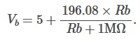 For example, if Rb is 2.7 MOhm, Vb = 148 V.
The bias output can sink or source an average current of 10 mA. However, there is no protection so care must be taken not to exceed the current limit. If more than 10 mA is required, the primary output of a second PDm200 can be used to generate the bias.
Enable/Shutdown
When the amplifier is Enabled and operating, the green LED is on. If the LED off, or flashing, the causes and associated test procedures are:
- The output current has been exceeded. Try reducing the frequency or voltage, or disconnect the load to test the module;
- The temperature limit has been exceeded. Check that sufficient air-flow is available, the fan is spinning, and the heatsink is not fouled with dust; or
- The supply voltage is not sufficient. Check the supply voltage. If the current rating is too small, some power supplies will continually cycle.
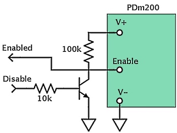
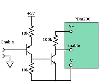
The Enable pin is a high impedance signal that floats 5V above the negative supply rail. It can be pulled to the negative supply rail to disable the amplifier. The voltage on this pin can also be monitored to check the status of the amplifier. Any monitoring circuit should have an input impedance of greater than 200 kOhm. A high level voltage on the enable pin indicates a normal status while a low level indicates a thermal shutdown.
The recommended enable circuits for unipolar and bipolar supplies are shown below. Any small signal transistors are suitable, e.g. BC817 and BC807.
Overload Protection
The PDm200 is protected against over-current and thermal overload. If the PCB temperature exceeds 70 degrees C the amplifier will be disabled until the temperature reduces.
Warranty
PDm200 devices are tested prior to delivery. There is no warranty period. Continually exceeding the operating specifications, e.g. by repeatedly exceeding the current limit, will destroy the module. The PDm200 modules are not considered repairable.
High Voltage Safety Warning
This product produces potentially lethal voltages up to 220 Vdc.
Observe Low-Voltage (as per ANSI C84.1-1989) safety precautions, e.g.
- Use an observer trained in low-voltage rescue
- Do not operate with exposed conductors
- Use appropriate signage
Certifications and Compliance
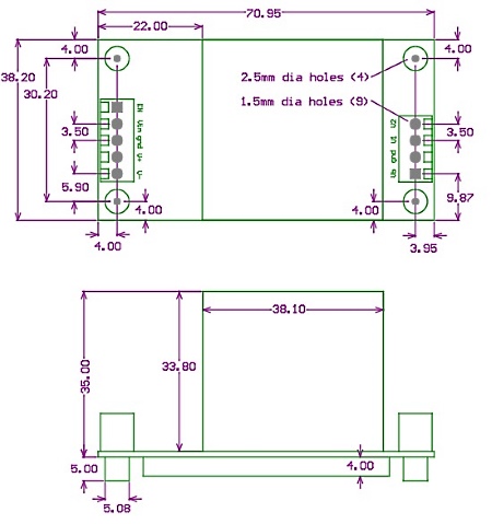
Dimensions
The mounting posts accept an M2.5 screw. For the PCB mounting version (PDm200-PCB), an Altium schematic and footprint library is available for download. The PCB pin part numbers are Phoenix Contact PST 1.0/5-3.5 and PST 1.0/4-3.5 which are 1 mm diameter, the recommended PCB hole is 1.5 mm. PCB mounting modules can be soldered directly to a board, or mounted with pin receptacles such as Harwin H3161-05.
Click here to download 3D model
How to order
Request a quote for this product by sending an e-mail through "Request for Quote" referencing the part number or by calling us at 814-861-5688 (8:30am to 5:30pm EST).