PD32 - 32 Channel Piezo Driver
Piezoelectric Drivers
 PD32 Users Manual
 Calculate Power Bandwidth (Grounded Load)
Calculate Power Bandwidth (Floating Load)
Specifications:
| Electrical Specifications | |||
|---|---|---|---|
| Grounded Load |
Floating Load |
||
| Output Voltage | +45 V to +130 V | +/-90 V to +/-130 V | |
| Peak Current | 150 mA per channel | 75 mA per channel | |
| RMS Current | 106 mA per channel | 53 mA per channel | |
| Power Bandwidth | 50 kHz (120Vp-p) | 50 kHz (240 Vp-p) | |
| Signal Bandwidth | 120 kHz | 120 kHz | |
| Slew Rate | 19 V/us | 38 V/us | |
| Gain | 15 V/V | 20 V/V | |
| Input Impedance | 53 kOhm | 6.25 kOhm | |
| Input Offset | +/- 5mV | +/- 5 mV | |
| Load | Unlimited | Unlimited | |
| Output Noise | 200 uV RMS (1uF) | 300 uV RMS (1uF) | |
| Protection | Short circuit and thermal | ||
| Imputs | 32 Analog inputs, shutdown command | ||
| Outputs | 32 HV Analog outputs, overload monitor | ||
| Connectors | Industry standard DB-37 (input) and DD-78 (output) | ||
| Power | 85 Vrms to 305 Vrms, 50 or 60 Hz, IEC C14 connector | ||
| Mechanical Specifications | |||
|---|---|---|---|
| Environment | 0 - 40 C (32-104 F), Non-condensing humidity | ||
| Dimensions | 212 x 304.8 x 88 mm (8.35 x 12 x 3.46 in) | ||
| Weight | 2 kg (4.4 lb) | ||
Features
The PD32 is a high-bandwidth, low-noise amplifier for driving up to 32 piezoelectric actuators. The voltage range is configurable from +45V to +/-130V and includes asymmetric voltage ranges such as 0V to +130V. The PD32 works seamlessly with common multi-channel DAC cards and is easy to use with LabView and Simulink. The compact size and 19-inch rack compatibility provides a comprehensive off-the-shelf solution for driving tens, hundreds, or thousands of piezoelectric actuators.
The PD32 is designed for demanding applications such as Adaptive Optics, Acoustic Beam Forming, Materials Testing, Astronomy, Ultrasonics, and Vibration Control. With an output current of 150mA per channel, a large array of piezoelectric actuators can be driven simultaneously at high frequencies. Positive and negative high-voltage bias outputs are also included for compatibility with piezoelectric bender actuators.
Each channel is individually protected against short circuit and thermal overload. Status indicators on the front panel provide individual monitoring of all channels. A digital status signal and external shutdown command is also accessible from the input connector to allow remote monitoring and control. The input and output connectors are industry standard 37 Pin D-Sub connectors which are straight-forward to assemble. Adaptors are available for industry standard 32 Channel DAC cards.
Compatible Actuators
| Compatible Actuators | |||
|---|---|---|---|
| Stack Actuators | 60V, 100V, 120V, 150V | ||
| Plates and Tubes | up to +/-130V | ||
| Two Wire Benders | up to +/-130V | ||
| Three Wire Benders | up to 130V, or +/-65V | ||
Output Voltage Range
The output voltage range is configurable between +50V and +/-140V and the load can be either grounded or floating. For peak-to-peak voltages less than 140V, the grounded load configuration is recommended since this provides greater current. The floating load configuration is required for the +/-100V and +/-140V ranges. The desired configuration should be specified at the time of ordering.
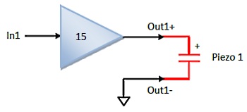
Grounded Load Configurations
In the grounded load configurations, the actuator connections are illustrated below. The negative output is internally grounded.
The desired output voltage range can be selected from the following table.
| Min Voltage | Max Voltage | Order Code |
|---|---|---|
| 0 | +130 | PD32-V0,130 |
| 0 | +120 | PD32-V0,120 |
| 0 | +95 | PD32-V0,95 |
| 0 | +70 | PD32-V0,70 |
| 0 | +45 | PD32-V0,45 |
| -15 | +115 | PD32-V15,115 |
| -20 | +95 | PD32-V20,95 |
| -45 | +45 | PD32-V45/45 |
| -65 | +65 | PD32-V65,65 |
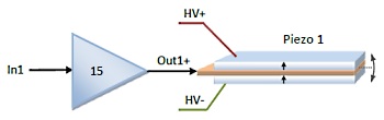
Three wire bender actuators can be driven using the following connection diagram. The HV+ and HV- bias voltages are the minimum and maximum voltages listed in the table above and are accessible on the output connector.
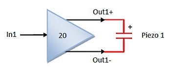
Floating Load Configurations
The floating load configuration is useful for achieving higher peak-to-peak voltage swings. The connection diagram is illustrated below. Do not connect either of these signals to ground, for example, to the ground terminal of an oscilloscope probe.
The desired output voltage range can be selected from the following table.
| Min Voltage | Max Voltage | Order Code |
|---|---|---|
| -130 | +130 | PD32-V130,130 |
| -95 | +95 | PD32-V95,95 |
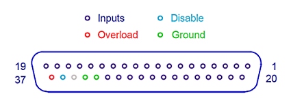
Input Connection Diagram
The front panel input connector is a DB37 Female Connector (Amphenol L77SDC37SA4CH4F). This connector is also recommended for use on customer PCBs connecting to the PD32 via a male-male DB-37 cable (included). The input connection diagram is illustrated below.
| Signals | Connector Pin | Notes |
|---|---|---|
| Analog Inputs 1 to 32 | 1 - 32 | +/-10V max |
| Ground | 33, 34 | |
| Not Connected | 35 | |
| Digital disable command | 36 | 3.3V or 5V logic |
| Overload indicator | 37 | 5V logic |
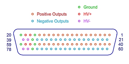
Output Connection Diagram
The front panel output connector is an industry standard DD78 Female Connector (Harting 09565527613). This connector is also recommended for use on customer PCBs connecting to the PD32 via a male-male DD-78 cable (included). The connection diagram is illustrated below.
| Signals | Connector Pin | Notes |
|---|---|---|
| Outputs 1 to 16 (positive) | Pins 1 - 16 | |
| Ground | 17, 20 | |
| HV+ | 18, 19 | For driving benders |
| Outputs 1 to 16 (Negative) | 21 - 36 | |
| Ground | 37 | |
| HV- | 38, 39 | For driving benders |
| Outputs 17 to 32 (Positive) | 40 - 55 | |
| Ground | 56, 59 | |
| HV+ | 57, 58 | For driving benders |
| Outputs 17 to 32 (Negative) | 60 - 75 | |
| Ground | 76 | |
| HV- | 77, 78 | For driving benders |
Output Current
The peak output current is 150 mA per channel in the grounded load configuration or 75 mA per channel in the floating load configuration. The maximum RMS current is 106 mA in the grounded configuration and 53 mA in the floating load configuration.
The maximum output current from all channels is 3 Amps RMS.
Power Bandwidth
Calculate Power Bandwidth (Grounded Load)
Calculate Power Bandwidth (Floating Load)
Power Bandwidth and Slew-Rate Limits
The nominal slew-rate of the PD32 is 19 V/us. Therefore, the maximum frequency sine-wave is
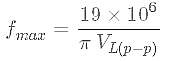
That is, the power bandwidth for a 120 Vp-p sine-wave is 50 kHz. In the floating load configuration, the slew-rate is doubled to 38 V/us, therefore, the power bandwidth for a 240 Vp-p sine-wave is 50 kHz.
With a capacitive load, the power bandwidth is limited by the output current. The maximum frequency sine wave is
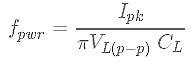
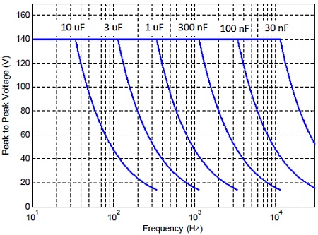
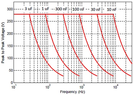
where Ipk is the peak current limit, VL(p-p) is the peak-to-peak output voltage, and CL is the effective load capacitance. The power bandwidth versus load capacitance is listed below.
| Load | Peak to Peak Voltage (Grounded) | |||
|---|---|---|---|---|
| Cap | 50 | 100V | 130V | |
| 10 nF | 95 kHz | 47 kHz | 34 kHz | |
| 30 nF | 31 kHz | 15 kHz | 11 kHz | |
| 100 nF | 9.5 kHz | 4.7 kHz | 3.4 kHz | |
| 300 nF | 3.1 kHz | 1.5 kHz | 1.1 kHz | |
| 1 uF | 950 Hz | 470 Hz | 340 Hz | |
| 3 uF | 310 Hz | 150 Hz | 114 Hz | |
| 10 uF | 96 Hz | 48 Hz | 34 Hz | |
| 30 uF | 32 Hz | 16 Hz | 11 Hz | |
| Load | Peak to Peak Voltage (Floating) | |||
|---|---|---|---|---|
| Cap | 100 | 200V | 260V | |
| 10 nF | 23 kHz | 11 kHz | 8.5 kHz | |
| 30 nF | 7.9 kHz | 3.9 kHz | 2.8 kHz | |
| 100 nF | 2.3 kHz | 1.1 kHz | 850 Hz | |
| 300 nF | 790 Hz | 390 Hz | 284 Hz | |
| 1 uF | 230 Hz | 119 Hz | 85 Hz | |
| 3 uF | 80 Hz | 40 Hz | 28 Hz | |
| 10 uF | 24 Hz | 12 Hz | 9 Hz | |
| 30 uF | 8 Hz | 4 Hz | 3 Hz | |
In the following figures, the maximum frequency periodic signal is plotted against the peak-to-peak voltage.
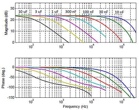
Small Signal Bandwidth
The small-signal bandwidth and frequency response is described in the following table and figure.
| Load Cap. | Bandwidth |
|---|---|
| No Load | 120 kHz |
| 10 nF | 90 kHz |
| 30 nF | 40 kHz |
| 100 nF | 11 kHz |
| 300 nF | 3.8 kHz |
| 1 uF | 1.0 kHz |
| 3 uF | 320 Hz |
| 10 uF | 62 Hz |
| 30 uF | 24 Hz |
Overload Protection / Shutdown
Each channel is protected against short-circuit and thermal overload. If the thermal overload on any channel engages, the front panel indicator for that channel will illuminate. In addition, an overload on any channel will cause the overload signal (pin 37) on the input connector to go high (+5V).
The amplifier can also be disabled by applying a logic high (3.3V to 5V) to the disable pin (pin 36).
Enclosure / Rack Mounting
The PD32 has a side air intake and rear exhaust. These vents should not be obstructed. If sufficient air-flow is not available, the amplifier will enter a thermal overload state as discussed above.
A single PD32 amplifier can be mounted in 19-inch rack using the single rack kit which includes a spacer, fasteners, and mounting handles (Order code: SingleRackKit-2U). This can be ordered with the amplifier, or separately and retrofitted to any PD32 amplifier. Simple assembly is required.
Two PD32 amplifiers can be rack mounted in a side-by-side arrangement using the double rack kit which includes alternate side panels, fasteners, and mounting handles (DoubleRackKit-2U). This should be ordered with a set of two amplifiers; however, a retrofitting kit for existing amplifiers is available on request. Some assembly is required.
Input Test Connector and Cable
An adaptor PCB is supplied which connects all input channels to a single BNC connector. A 2.5ft DB37 (Male-Male) input cable is also supplied.
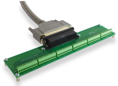
Breakout Board (PD32-Breakout)
A screw-terminal breakout board is included which connects to the amplifier via a Female DD78 connector (TE 5748483-5) and HD78 Male-Male cable (2.5 ft). If required, the board can be mounted onto a base structure using the installed M3 hex spacers.
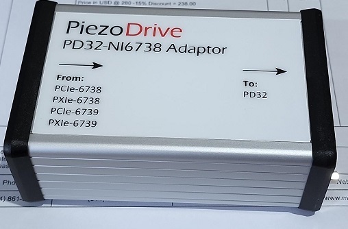
Signal Adaptors
The signal adaptors allow a direct connection to common multi-channel DAC cards. Standard adaptors are listed below; however, custom adaptors can also be created.
| Manufacturer | DAC Card | Signal Adaptor | Notes |
| Natlional Inst. |
PCIe-6738 and |
PD-6738 | Req. NI SHC68-68-A2 Cable |
| National Inst. |
PCIe-6739 and |
PD-6738 | Req. NI SHC68-68-A2 Cable |
| National Inst. |
PCI-6723 and |
PD-6723 | Req. NI SHC68-68-A2 Cable |
The adaptors are contained in a compact enclosure that is mounted inline with the PD32 input cable and DAC card output cable.
Standard Delivery Contents
- PD32 Amplifier with chosen configuration, e.g. PD32-V0,130
- Input Test PCB
- Output screw-terminal breakout board
- Input cable – DB37 Male-Male, 2.5ft (CS-DSDMDB37MM-002.5)
Output cable – HD78 Male-Male, 2.5ft (CS-DSDHD78MM0-002.5) - IEC C13 Power cable with suitable connector for shipping destination
Safety
This device produces hazardous potentials and should be used by suitably qualified personnel. Do not operate the device when there are exposed conductors.
Warranty
The PDC32 is guaranteed against manufacturer defects for a period of 12 months.
Previous Versions
Version 4, Revision 1, Manual (Shipped 01/02/2020 – 15/02/2024)