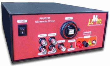
PDUS200 Ultrasonic Driver
Piezoelectric Drivers
 PDUS200 Specifications
PDUS200 Manual
Features
The PDUS200 is a complete solution for driving precision and high-power ultrasonic actuators. The PDUS200 uses a digital phase-locked loop to actively seek and track a selected actuator resonance in real-time. This approach provides fast and precise control of the actuator resonance with the option to operate slightly off resonance where the actuator dynamics are less sensitive to load forces. An optional power control module is also available that provides real-time closed-loop control of the dissipated actuator power. For example, if the actuator power is set to 30W, the amplifier will automatically regulate the applied voltage to maintain 30W dissipation. Power tracking can reduce or eliminate the effect of variable cutting forces on the resonance amplitude.
Specifications:
| Electrical Specifications | |
|---|---|
| Frequency | 1 - 50kHz |
| Output Voltage | +/- 100V (Customizable) |
| Output Current | +/- 4A |
| Transducer Power | 200W |
| Slew Rate | 35 V/us |
| Overload | Thermal and Overcurrent Protection |
| Analog Outputs | Voltage and Current Monitors |
| Analog Inputs | Analog Inputs and vibration signal |
| Analog Gain | 15 V/V |
| Output Connectors | LEMO 0B Socket 4mm Bananna Sockets |
| Power Supply | 90 Vac to 250 Vac |
Digital Specifications:
| Digital Specifications | |
|---|---|
| USB | 2.0 |
| Frequency Resolution | 1 MHz |
| Phase Resolution | 0.1 Degrees |
| Sampling Rate | 1 MHz |
| Digitized Signals | Voltage, Current, Auxiliary |
| Amplifier Shutdown | USB or Digital (Via BNC) |
| Programming Interface | Windows API |
Mechanical Specifications:
| Mechanical Specifications | |
|---|---|
| Environment | -40C to 60C (-40 to 104F) |
| Dimensions | 304.8 x 212 x 88 mm (L x W x H) |
| Weight | 2.5 kg |
The user interface of the PDUS200 is shown below. The actuator voltage and current, together with the optional external vibration signal is plotted in the upper right corner. On the bottom right corner, the time history of the frequency and phase is recorded.
The amplifier can also record an auxiliary signal from an accelerometer or vibrometer. This allows the impedance and mechanical frequency response of the transducer to be characterized with the built-in swept-sine analysis functions.
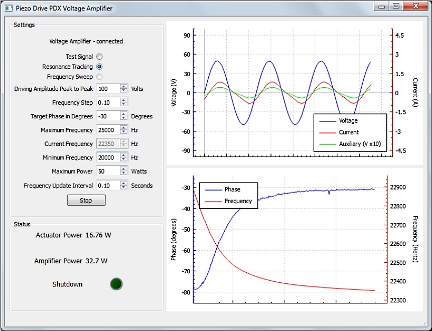
Software interface during resonance tracking.
Click image to enlarge
The PDUS200 generates a pure sine-wave output which avoids the excitation of secondary resonance modes by the drive harmonics. The internal signal generator and resonance tracking are configured and monitored via a USB interface and desktop application. Functions include signal monitoring, power monitoring, resonance tracking, and frequency response analysis of the transducer impedance. A USB API provides third-party applications with comprehensive control over the amplifier and full access to all digital signals and logic.
Applications include ultrasonic drilling and cutting, medical devices, dental devices, ultrasonic testing, liquid cavitation, and vaporization. The PDUS200 can be used as a standalone instrument or as a component in an OEM machine. Customized voltage and current ranges are also possible.
Software Functions
In the standard operating modes, all signals are displayed on a dashboard along with a time history of the transducer resonance frequency and phase. Parameters such as the operating voltage, target phase, and frequency limits, can be set though the user interface.
The built-in swept-sine frequency response analyzer (shown below) allows the actuator's electrical and mechanical response to be characterized. This feature is particularly useful for transducer development, troubleshooting, and health monitoring in industrial machinery.
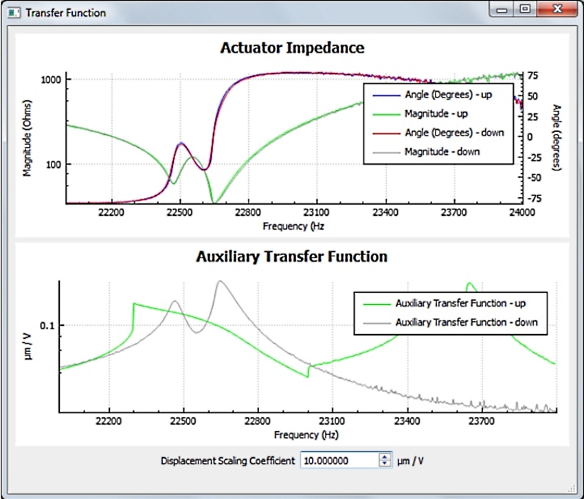
Characterization of the electrical and
mechanical frequency responses.
Click image to enlarge
Applications Programming Interface
The applications programming interface allows a third party Windows application to detect and control the amplifier without any software installation or USB drivers. Simple function calls initialize the amplifier and check the status. The electrical and mechanical signals can also be read from the amplifier and plotted in a third-party application. Source code for the desktop application is provided to allow customization and to demonstrate the use of API function calls.
Real-time Power Control Option (PDUS200-PWR)
With the real-time power control option, a second resonance tracking mode is available where the amplifier will adjust the operating voltage to maintain a constant actuator power. Real-time power control is active while the amplifier is operating at the actuator resonance frequency. Arbitrary minimum and maximum voltage limits can be set through the software interface.
Customized Voltage and Power Ranges
The PDUS200 output voltage range can be readily customized from 10V to 1000V through the addition of an internal step-up or step-down transformer. The output power remains at 200W so the peak output current is 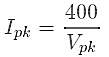
For example, with an output voltage of ±500V, the output current is ±0.8A.
The output power can also be increased by using multiple amplifiers. In this configuration one PDUS200 unit provides all of the control functions and any number of slave units are used for increasing the power by multiples of 200W. The amplifier outputs are combined using an external junction box which may also contain isolating or step-up/down transformers. Using this method, output powers exceeding 1kW are readily achievable.
Overload Protection
The Shutdown indicator will illuminate during a shutdown caused by a current overload or if the amplifier overheats as a result of excessive ambient temperature, poor air-flow, or fan failure. During shutdown, the amplifier output current is limited to a few mA and may float to the high or low voltage rail if the load impedance is high. When the amplifier is turned on, the overload protection circuit is engaged by default and will take approximately three seconds to reset.
In addition to the internal shutdown triggers, the output stage of the amplifier can also be disabled by applying a positive voltage to the external shutdown connector (2V to +12V). The impedance of the external shutdown input is approximately 2.5 k?.
Enclosure
The PDUS200 Driver has a side air intake and rear exhaust. These vents should not be obstructed. If sufficient air-flow is not available, the amplifier will enter a thermal overload state as discussed above. The PDUS200 amplifiers can be bolted together in a side-by-side two-channel arrangement. With the addition of rack-mount handles, this configuration can be mounted into a standard 19-inch rack. A 19-inch rack-mount kit is also available for a single amplifier.