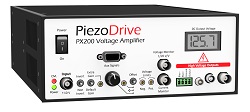
PX200 - 140W Voltage Amplifier
Piezoelectric Drivers
 PX200-V5 Users Manual
 Calculate Power Bandwidth
Specifications:
| Electrical Specifications | |||
|---|---|---|---|
| Slew Rate | 35 V/us | ||
| Signal Bandwidth | 390 kHz | ||
| Max Power | 140 W Dissipation | ||
| Load | Any | ||
| Noise | 150 uV RMS (10 uF Load, 0.03 Hz to 1 MHz) | ||
| Protection | Continuous short-circuit, thermal | ||
| Voltage Monitor | 1/20 V/V (BNC) | ||
| Current Monitor |
1.5 V/A if peak current is 6 Amps or less
0.5 V/A if peak current is greater than 6 Amps
|
||
| Input Impedance | 48.7 kOhms | ||
| Output Impedance | 1.5 Ohms | ||
| Output Connectors | LEMO 0B, LEMO 00, Screw Terminals, BNC | ||
| Power Supply | 90 Vac to 250 Vac | ||
| Mechanical Specifications | |||
|---|---|---|---|
| Environment | 0 - 40 C (32-104 F), Non-condensing humidity | ||
| Dimensions | 212 x 304.8 x 88 mm (8.35 x 12 x 3.46 in) | ||
| Weight | 2 kg (4.4 lb) | ||
Features
The PX200 is a low-noise high-current linear amplifier for driving piezoelectric actuators and other loads. The output voltage range can be unipolar, bipolar, or asymmetric from 50V to 200V. Refer to the specifications table for the available output voltage ranges. Two amplifiers can be connected in bridge-mode to provide up to +/-200V or +400V. The PX200 has a high output current up to 13 Amps peak and is well suited to precision applications that require high power and frequency.
The PX200 can drive any load impedance including unlimited capacitive loads such as stack actuators; standard piezoelectric actuators; two wire benders; and three-wire piezoelectric benders requiring a bias voltage. Bias voltages can be generated using two auxiliary outputs linked to the power supply voltages.
A range of front panel controls provide maximum application flexibility, these include input signal inversion, variable gain, DC offset, and variable voltage limits. A 9-pin DSUB connector on the front panel includes signals for the input, voltage monitor, current monitor, shutdown monitor, and shutdown command. A four-digit LCD screen also displays the DC voltage.
The output connectors include BNC, LEMO 00, LEMO 0B.302, and plug-in screw terminals. The PX200 is suited to a wide range of applications including electro-optics, ultrasonics, vibration control, nanopositioning systems, and piezoelectric motors.
| Compatible Actuators | |||
|---|---|---|---|
| Stack Actuators | Up to 200V | ||
| Plates and Tubes | +/-100V or +200V | ||
| Two Wire Benders | +/-100V or +200V | ||
| Three Wire Benders | Up to +200V with +200V bias, or +/-100V with +/-100V bias | ||
Output Voltage Range
The output voltage range is specified when ordering. The standard voltage ranges and associated current limits are listed below. Since the PX200 has front panel controls for reducing the positive and negative output voltage range, choose a range equal to or slightly greater than required.
| Neg. Volt. (V) |
Pos. Volt. (V) |
RMS Curr. (A) |
Peak Curr. (A) |
Pulse Curr. (A) |
Gain [1] |
Var [2] |
Order Code [3] |
|---|---|---|---|---|---|---|---|
| 0 | 200 | 1.6 | 3 | 9 | 20 | A | PX200-P200 |
| 0 | 150 | 2.1 | 4 | 10 | 15 | A | PX200-P150 |
| -50 | 150 | 1.6 | 3 | 9 | 15 | A | PX200-N50-P150 |
| -50 | 100 | 2.1 | 4 | 10 | 10 | A | PX200-N50-P100 |
| -100 | 100 | 1.6 | 3 | 9 | 10 | A | PX200-N100-P100 |
| -100 | 50 | 2.1 | 4 | 10 | 10 | A | PX200-N100-P50 |
| -100 | 0 | 3.1 | 6 | 13 | 10 | A | PX200-N100 |
| -150 | 0 | 2.1 | 4 | 10 | 15 | A | PX200-N150 |
| -200 | 0 | 1.6 | 3 | 9 | 20 | A | PX200-N200 |
| 0 | 175 | 1.8 | 3 | 10 | 20 | B | PX200-P175 |
| -25 | 150 | 1.8 | 3 | 10 | 15 | B | PX200-N25-P150 |
| -25 | 100 | 2.7 | 3 | 9 | 15 | B | PX200-N25-P100 |
| -75 | 100 | 1.8 | 3 | 10 | 10 | B | PX200-N75-P100 |
| -75 | 50 | 2.7 | 4 | 10 | 10 | B | PX200-N75-P50 |
| 0 | 125 | 2.7 | 4 | 10 | 15 | D | PX200-P125 |
| -25 | 125 | 2.1 | 4 | 10 | 15 | D | PX200-N25-P125 |
| -75 | 75 | 2.1 | 4 | 10 | 10 | D | PX200-N75-P75 |
| 0 | 100 | 3.1 | 6 | 13 | 10 | E | PX200-P100 |
| 0 | 75 | 4.1 | 6 | 13 | 10 | E | PX200-P75 |
| 0 | 50 | 5.3 | 9 | 13 | 10 | E | PX200-P50 |
| 0 | 25 | 5.3 | 9 | 13 | 10 | E | PX200-P25 |
| -25 | 75 | 3.1 | 6 | 13 | 10 | E | PX200-N25-P75 |
| -25 | 50 | 4.1 | 6 | 13 | 10 | E | PX200-N25-P50 |
| -25 | 25 | 5.3 | 9 | 13 | 10 | E | PX200-N25-P25 |
| -50 | 50 | 3.1 | 6 | 13 | 10 | E | PX200-N50-P50 |
| -50 | 25 | 4.1 | 6 | 13 | 10 | E | PX200-N50-P25 |
| -50 | 0 | 5.3 | 9 | 13 | 10 | E | PX200-N50 |
| -75 | 0 | 4.1 | 6 | 13 | 10 | E | PX200-N75 |
| -100 | 0 | 3.1 | 6 | 13 | 10 | E | PX200-N100 |
- [1] Refer to Section 6 for details on the pulse current limit
- [2] The gain can be increased by up to another factor of 10 using the front panel control
- [3] The variant is the hardware version required for the chosen configuration
Power Bandwidth
The online power bandwidth calculator estimates the highest achievable frequency with a capacitive load impedance. The calculator considers the current limit, slew-rate, output impedance, and small-signal bandwidth.
Calculate Power Bandwidth
With a capacitive load, the maximum operating frequency due to RMS current limit is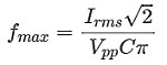
where Irms is the current limit, Vp-p is the peak-to-peak output voltage, C is the load capacitance. The above equation is also true for any periodic waveform, including triangle waves and square waves.
The ‘power bandwidth’ is the maximum frequency at full output voltage. When the amplifier output is open-circuit, the power bandwidth is limited by the slew-rate; however, with a capacitive load, the maximum frequency is limited by the RMS current and load capacitance. The power bandwidth for a range of capacitive loads is listed below.
| Load | 50 Vp-p |
75 Vp-p |
100 Vp-p |
125 Vp-p |
150 Vp-p |
175 Vp-p |
200 Vp-p |
|---|---|---|---|---|---|---|---|
| 10 nF | 222930* | 148620* | 111465* | 89172* | 74310* | 63694* | 55732* |
| 30 nF | 222930* | 148620* | 111465* | 89172* | 74310* | 63694* | 55732* |
| 100 nF | 222930* | 148620* | 111465* | 89172* | 62000 | 45714 | 35000 |
| 300 nF | 160000 | 82667 | 46667 | 32000 | 20667 | 15238 | 11667 |
| 1 uF | 48000 | 24800 | 14000 | 9600 | 6200 | 4571 | 3500 |
| 3 uF | 16000 | 8267 | 4667 | 3200 | 2067 | 1524 | 1167 |
| 10 uF | 4800 | 2480 | 1400 | 960 | 620 | 457 | 350 |
| 30 uF | 1600 | 827 | 467 | 320 | 207 | 152 | 117 |
In the above table, the frequencies limited by slew-rate are marked with an asterisk. The slew-rate is approximately 35 V/uS which implies a maximum frequency of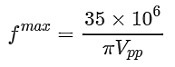
Small Signal Bandwidth
The small-signal frequency response and -3 dB bandwidth is described in the Figures 1 and Table 3
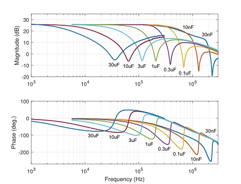
| Load Cap | Bandwidth |
|---|---|
| 10 nf | 393 kHz |
| 30 nf | 431 kHz |
| 100 nf | 367 kHz |
| 300 nf | 208 kHz |
| 1 uf | 88 kHz |
| 3 uf | 30 kHz |
| 10 uf | 9.3 kHz |
| 30 uf | 3.7 kHz |
| 110 uf | 1.3 kHz |
Noise
The output voltage noise contains a low frequency component (0.03 Hz to 20 Hz) that is independent of the load capacitance; and a high frequency (20 Hz to 1 MHz) component that is approximately inversely proportional to the load capacitance.
The noise is measured with an SR560 low-noise amplifier (Gain = 1000), oscilloscope, and Agilent 34461A Voltmeter. The low-frequency noise is plotted in Figure 4. The RMS value is 120 uV with a peak-to-peak voltage of 600 uV.
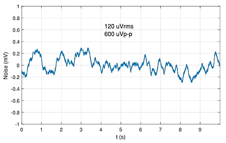
The high frequency noise (20 Hz to 1 MHz) is listed in the table below versus load capacitance. The total RMS noise from 0.03 Hz to 1 MHz is found by summing the RMS values, that is  For a load capacitance of less than 1 uF, the noise is primarily broadband thermal noise; however, for a capacitance of greater than 1 uF, the noise is primarily due to low-frequency noise.
| Load Cap. | Bandwidth | HF Noise RMS | Total Noise RMS |
|---|---|---|---|
| 10 nf | 393 kHz | 530 uV | 543 uV |
| 30 nF | 431 kHz | 586 uV | 598 uV |
| 100 nF | 367 kHz | 689 uV | 699 uV |
| 300 nF | 208 kHz | 452 uV | 468 uV |
| 1 uF | 88 kHz | 261 uV | 287 uV |
| 3 uF | 30 kHz | 106 uV | 160 uV |
| 10 uF | 9.3 kHz | 56 uV | 132 uV |
| 30 uF | 3.7 kHz | 52 uV | 131 uV |
| 100 uF | 1.3 kHz | 47 uV | 129 uV |
Bridged Mode
In bridged mode, the load is connected between the outputs of two amplifiers, which doubles the output voltage span and power. Grounded loads cannot be driven using bridged mode. Care should be taken not to connect the negative side to ground accidentally, for example, by using a grounded oscilloscope probe.
Figure 3 shows how two amplifiers are connected to achieve +/-200V across a load. A +/-10V signal is applied to both amplifiers, and the bottom amplifier is configured in inverting mode. The total voltage across the load is +/-200V and the effective gain is twice the gain of a single amplifier. Common bridged-mode configurations are listed in Table 5.
The current limits in bridge mode are identical to normal operation. The power bandwidth calculator can also be used for predicting bridge-mode performance by entering the total voltage across the load. For the example in Figure 3, the total peak-to-peak output voltage is 400V. When entering this value to the calculator, an error will be shown since 400V is greater than the voltage span of a single amplifier; however, the calculator output is remains valid.
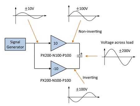
| Load Voltage | RMS Current | Non-Inverting Amp | Inverting Amp |
| ±200V | 1.5 A | PX200-N100-P100 | PX200-N100-P100 |
| ±100V | 3.1 A | PX200-N50-P50 | PX200-N50-P50 |
| 0V to 200V | 3.1 A | PX200-P100 | PX200-N100 |
| 0V to 300V | 2.0 A | PX200-P150 | PX200-N150 |
| 0V to 400V | 1.5 A | PX200-P200 | PX200-N200 |
Delivery Contents
- PX200 amplifier with plug-in screw terminal installed
- IEC C13 power cable, suited to the shipping destination
Warranty
PiezoDrive amplifiers are guaranteed for 12 months from the date of delivery. The warranty does not cover damage due to misuse.
Previous Versions
| Hardware Version | Manufactured | Manual |
|---|---|---|
| V1 | 2014-2017 | Download User Manual |
| V2 | 2017-2022 | Download User Manual |